Thursday, 5 May 2011

Wednesday 13th April 2011

Acrylic Flower
Taking inspiration from one of Orla Kiely's designs I used 2D design to create an Acrylic picture.


I rounded the square corners.


...And separated all of the shapes...

So that they could each be individually be cut out by the laser cutter.

The thick lines are used for etching and the thin lines for cutting through the material (acrylic)


Wooden Clock
Again using the shapes and setting the page size to the piece of ply wood I had, the laser cutter cut the basic clock features.

CNC Engraving Machine


I used the text in the left hand tool bar. This made the machine engrave incredible slowly because it thinks that the letter which are black need to be all cut out, I would have been better using the Techsoft Text with a thicker needle.

Wednesday, 6 April 2011

Wednesday 23rd March 2011

Tutorial 14 - Bitmap to Vector Conversion

Imported Bitmap image, using the select and clip tool and set the parameters to the area I wanted to clip (logo). "Trim - Delete excess data" "Clip Outside"


Selected the 'Vectorise' tool (Left hand toolbox) and transformed the image. During this process, the vectorisation colour dialogue box opens; which allows you to change the colour. In this case 'monochrome' (Black and White).

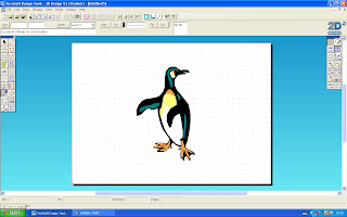
A more complicated image to change was the penguin. Made up of a wider range of colours and shades. 

Again using the vectorise tool. However, this time there were 13 colours, to make the converted image much simpler, removing the top shade in the palette left the image with 6 colours. 


During the conversion, the background is removed.


Tutorial 16 - Double Lines
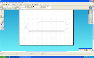
This tutorial was pretty self explanatory. Using the different arcs and lines within the 'Double Path' icon. 

Outer area of the paper clip produced from 'Open line', 'Open Arc', 'Open line', 'Open Arc' (But smaller - so the next line goes within the shape already produced.)...


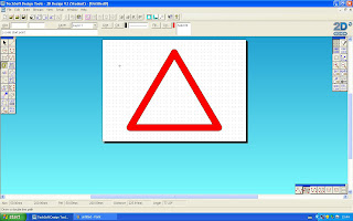
Again using the 'Open Line' and 'Open Arc' tools, the warning sign can be made.

The ends of the lines were changed to Triangle and the double line filled with solid red.


Tutorial 18 - Scaling and Drawing to Scale
The settings of the grid were changed to metres instead of Millimetres. This garage is drawn to a scale of 1:20. 

Tutorial 19 - Grouping and Adding

The grouping in 2D design is pretty much the same as any other program. Selecting images and grouping them together in the edit menu.


The chair was moved into position then rotated around the table at 70 degrees.


Final Office Plan


Tutorial 21 - 3D Effects and Exploding
Basic outline of a camera...


Using the 'perspective with double vanishing points' tool allows the 2D shape to be transformed...

Producing a 3D view of each of the three main shapes.

Selecting the depth and angle for the 3D shape to be produced. The trapezium is transformed into 3D.


Exploding the shapes gave them the 3D look, however with all the lines from each shape, therefore, to make the camera more realistic I used the Delete part to remove lines to leave the final sketch.

Wednesday 16th March 2011

Tutorial 13 - Clipping an image to Fit a Shape

I imported the box net, then the gorilla picture on top. (Importing it - but then it needs to be sent to the back, behind the net) 

Using the select tool, I positioned the picture within the area I wanted it to be cropped to. 
The clip path by locating boundary tool, also found in the left toolbox, is used to select the boundary and area in which I wanted the picture to be cropped. 
Ensuring the picture is selected, and using the Clip settings options, I made sure  the outer area of the photo is going to be cropped. "Mask - Hide excess data" and  "Clip Outside".

Final Result

Tuesday 8th March 2011

Tutorial 10 - Text

Linear Text (chosen from the left hand toolbar). The text is written CAD < return > TEXT. Although the two words appear to be on two separate lines they're actually still together. 

Once the text Is highlighted the Start Edit/Property tool box appears in the bottom right corner. I opened this and filled in the text. I did this in four sections. 
Once the linear text box is open, I highlighted the first letter and changed its colour to Red, then highlighted the second letter and went into Start Edit/ Property again to change the individual colour. Adding drop shadows too.


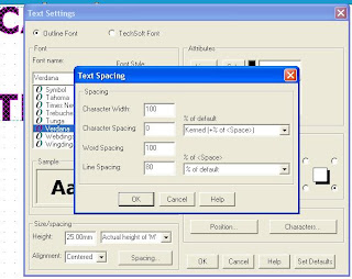
The line spacing can be changed.


Tuesday 15th February 2011

 Tutorial 4 - Object Selection and the Marquee Box
Each yellow square when a shape is selected has different uses:

The centre square allows the box (shape) to be moved around.

The circle at the right of the marquee box allows the shape to be rotated.

The diamond to the left of the marquee box allows the shape to be flipped vertically ...

...and the diamond to the at the top of the square flips the shape horizontally.


The double diamonds at the bottom of the shape copy it.


Tutorial 7 - Line Styles and Line Colours

The line type can be changed from solid to dashes and the thicknesses of lines. (Fine and Thick)


Tutorial 8 - Using Fills
I practiced filling shapes with different coloured fills.

Selecting different shape patterns allows for the different areas to be filled in making a picture.


Tutorial 9 - Creating New fills
I created a new fill. Setting it to a gradual fill pattern. I added two colours so there are four on the bar. (Red, White, Red and Black) and the pattern to linear with a 8mm space.


I created  a second fill pattern of my own. Using purple, red, orange and yellow. But this time the pattern is radial.

Using the duck, mesh and my own radial pattern I filled the shapes with the patterns.

Friday, 4 March 2011

Thursday 27th January 2011

2D Design
  • Tutorial 12 - Loading a Bitmap Image and Clipping It (Apple)

Imported picture of the fruit bowl, ready for editing. 

After this screen shot was taken I zoomed in around the apple to enlarge it. 
Using the Clip path tool (selecting it to Close Curve) I drew a path around the shape of the apple.

Once I had made the path I selected it and opened start edit. I slightly altered the shape by changing the nodes, I had to add a couple of nodes. 

To clip the apple to a standalone shape/picture I used the clip path tool and selected 'Mask - Hide excess data' and 'Clip outside'.
The background of the apple is cropped. 

  • Tutorial 5 - Editing and Drawing (Fish)
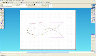
Using the select tool from the left toolbar and Start Edit function. The nodes of the line appear, these can then be moved and shaped as required. The centre spot is the point at where the line will be moved and the two dotes at each side (nodes) can be moved to alter the shape (curve) of the line. 

In start edit, you can still use the select tool to select certain areas, in this case the tail. Selecting an individual line allows this area to be moved without breaking the connections.

In start edit, one of the lines can be selected and a node can be added simply by clicking the option in the 'start edit' toolbar.


Thursday 13th January 2011

2D DESIGN
  • Getting to know the basic tools in 2D Design
The 2D Design Software Screen


Learning a Couple of the basic tools before proceeding with the tutorials provided by the software.
    The first tool I learnt about in 2D Design was the fact that the grid (10mm squared) can be taken off the background and put back on.
    There are then two locks which can be selected between:

Step Lock (above left) allows the cursor to lie between the dots (10mm squares) on the page; whereas, Grid Lock (above right) enables the cursor to only select the points and make connections from one to another. These two locks are selected from the right hand toolbar. You do not have to have a lock on. This means anywhere on the page can be selected.


  • Tutorial 3 - Basic Drawing

Using straight lines and the connection tools which are selected from the drag toolbar on each icon, I tried out each tool with and without the different locks.


Selecting a specific area and clicking on the Zoom In icon, zooms in the area to fit to the whole screen. You can then zoom out again quickly using the Zoom last icon. 


Using the connection tool and the Radial lock allows the angles to be 45 degrees only! The radial lock icon is in the right hand toolbar.


    The attach tool, found in the right hand toolbar allows separate lines and shapes to be joined together. Depending on the tool used to attach (straight line or arc) depends on the join (attachment). 

    I played around with the delete options. In 2D design it can sometimes be quite annoying that you cannot undo a series of steps. It only allows the last thing done to be undone, otherwise there are different tools for deleting. 

    • Tutorial 6 - Transformations (Flower)


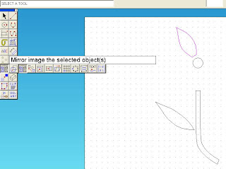
    Selecting the petal on the left, and choosing the Mirror Image transformation tool. Making sure the grid lock was on I drew the centre of symmetry down the stalk. The settings of the transformation were set to repeat. Therefore a new leaf is flipped to the other side of the stem.
    To create the petals around the centre of the flower.

    Using the mirror transformation tool selected from the left toolbar.

    Changing the settings to repeat and the rotation angle to 60 degrees. Also how many more of the repeated shapes wanted.


    The petals were then repeated and rotated around the flower centre.


    Tutorial 15 - Contours

    Contour lines have many different uses, they provide tool paths or graphical effects.

    The two hearts here demonstrate the two types of paths:
    On the left is the tool path, which produces a radius (round arc) around a point whereas, on the right shows the graphical path, which is the accurate contour line. 
    If I'd have carried on selecting the lines to contour, they would go round and round the shape until met in the centre.
    The contour spacings can be changed. The butterflies wings are set to 5mm as opposed to 10mm in the heart shapes.

    Again this butterfly shows the tool path contour lines.

    The cube net here can have its outside contour line extracted so the inner lines aren't seen.
    The net is selected and the contour line spacing set to 0 as I wanted the exact replica of the net outside lines shape. 

    I located the boundary (the outside of the net shape) which then produced the contour line.


    • Tutorial 17 - Construction Points
    Construction points can be used to divide a shape up. In this case the the curved trapezium. The number of divisions and the type of lines is selected. (10 divisions single lines)


    I then learnt how to control the construction points, enabling the settings were changed to 'construction point' so the lines could be attached. Using the attach tool joins up selected construction points on the shape

    Once I had learned how to use the construction points, I had a play around with circle, I set the circle to be split up into 13 sections at 30degrees each using the central point.

    • Tutorial 20 - Dimensioning and Layers
    I found this tutorial really useful, learning how to add dimensions to designs. There are three angles at which dimensions can be added, vertical, horizontal and diagonally.

    First of all I changed the name of one of the default layers to 'dimensions', so this enables me to store dimensions separate so the different layers could all be seen separate.


    As already mentioned there are three dimension angles; vertical, horizontal and diagonal.


    Once all of the dimensions had been added to the shape, turning off the dimensions layer turning of the visible and active parameters leaves just the dryer outline.


    Changing the dryer to invisible and inactive leaves just the dimensions.

    The layers are changed using the 'Layer...' function in the toolbar at the top of the programmes screen.